


Lighting control mode
There are various types of lighting control modes, including the following ones:
1. ON/OFF
This is the simplest and most common form of control: turn the lights on/off. This is also the way household appliances are switched on and off.
2. Silicon controller rectifier
A kind of dimming method is widely used locally, which has the advantage of no signal line distribution, relatively low cost and low requirements for electricians.
3. 0-10V
0-10V is also a kind of control of signal, used to control the power supply of the lamp, so that the lamp can accept the 0-10V signal, a simple understanding is to adjust the voltage to adjust the brightness, for example, 0V, the power output is 0, and when 10V, can let lamps output 100%brightness.
4. DALI
DALI
system is mainly used as the control system of hotel and indoor lighting, its
biggest feature is that a single lamp has and independent address, which can be
precisely controller by the DALI system.
5. DMX512
DMX512 is mainly used for stage lighting
and outdoor lighting.
The specific control form is : WIFI,
infrared induction, remote control, human body induction.
Next, i will share DMX512 with you.
What is DMX512?
DMX512 is Digital Multiplex With 512 pieces of information(That is, multi-channel digital transmission).
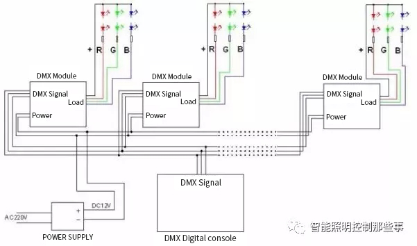
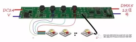
DMX 512 control system: several RGB lamps, each of which contains a DMX module inside. When the module receives power supply and controller signals at the same time, it will drive the LED lamp brightness change, so as to adjust the color change.
The characteristics of DMX512
1. Each output loop supports up to 512 channels.
RGB Single pixel luminaire connection diagram
For example, the output loop is the general, the communication is the soldier, and the equipment is the dormitory, according to the headquarters, each general can command a maximum of 512 soldiers, according to the number of soldiers contained in each dormitory, decided the number of jurisdiction of each general dormitory.
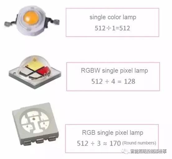
So how many lamps can a DMX512 port carry? How are channels calculated?
Single color:512
RGBW:512/4=128
RGB:512/3=170(Approximately)
2. 256-level dimming grayscales (0-255), Each DMX control byte is called an instruction frame, called a control channel, and can control one or more functions of the lighting device. A DMX instruction frame by a start bit, 8 data bits, and two end, total Ⅱcomposition, using one-way asynchronous serial transmission.
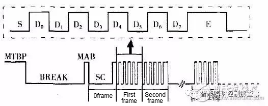
In the figure above, the S in the control instruction in the dotted line is the starting bit, and the width is one bit. E is the end bit and the width is two bits, representing the end of an instruction frame.
D0 and D7 are 8-bit control data, whose level combination has 256 states from 0000-1111 1111(corresponding to 0-255 of decimal number), when controlling the brightness of light, 256 brightness levels can be generated. 0000~(0)corresponds to the dimmest light, 1111 1111(255)corresponds to the brightest light. DMX512 instruction have a bit width(width per bit) of 4s, a frame width of 44 microseconds, and a transmission speed of 250kbps.
3. Standard EIA485 interface
The
connection mode is bus-type topology, which does not support ring or star
network up to 32 nodes can bu hooked up on the same bus. 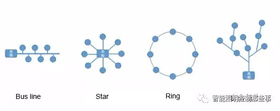
Transmission speed of 250kbps.
The bit rate is the number of bits Per Second(BPS) that are transmitted. The baud rate is closely related to the construction specification. And the high baud rate signal has relatively poor anti-interference ability.
DMX512 NOTE
In practical operation, it is not enough to understand the feature of DMX512, In order to avoid engineering accidents, we also need to remember the following five points for attention:
1、 The transmission distance of the super-five network cable is no more than 100 meters;
2、 when the distance between the controllers exceeds 100 meters, use optical fiber;
3、 EIA485 specifies that each repeater should carry no more than 32 nodes;
4、 The wiring of each control loop must follow the bus structure layout;
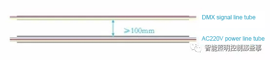
5、 Signal line and power line should be laid separately.
Murphy’s law
states that no matter how improbable, bad things will happen. Even if you
follow the steps and standards to use the DMX512 control system. You will
always encounter a variety of problems.
Common problems and solutions in project
debugging.
1. How to do the whole control circuit lamp random flash.
Confirm that the controller signal output is normal.
When the entire control loop lamp is out of control, if possible, the temporary controller should be used to test whether the circuit is controlled or not.
a. Controlled-Problem with original controller signal output(or wiring file problem, or port hardware problem, or port wiring problem)
b. Uncontrolled-continue to troubleshoot
c. Cut off the light after the
first light, test the first light separately to determine whether it is
controller problem or the signal interference from light behind it. At this
point, the first light is usually OK.
Troubleshoot trouble spots or lamps
When the controller signal output is normal, slowly add lamps to find out the nodes or lamps that lead to abnormal circuit signal, dichotomies are usually faster.
2. Individual lamps are not controlled in a control loop
Verify that the controller wiring is in place
The wiring file of the controller shall have the same number of lamps as the number of lamps installed on site.
Test with full wiring file
Use test program to undertake controlling test first, That is, single -port wiring files from 1 to 512 channels full fill.
a. Random flash lamp is controlled. At this time, the problem can be solved by re-coding the circuit lamp;
b. Individual lamps are still not controlled, check whether the wiring of signal output terminal of uncontrolled lamps is correct or there is qualityproblem of the lamps themselves;
3. When need to add a signal amplifier?
One function of the signal amplifier is to amplify the signal and restore the weakened signal to its original strength. The other function is to isolate the signal and prevent damage to the controller caused by lamp failure.
In standard case, according to EIS485 protocol, every 32 nodes need to add a signal amplifier. In order to avoid in rainy days or other circumstances the lamps signal is weak, thus the lamps random flash.
More than 32 DMX decoders need to be connected with a signal amplifier, the signal amplification can not be more than 5 times.
When the signal wire is longer or wire quanlity causes such a recoil effect, can try connect 0.25W 90-120Ω terminal resistance to the DMX decoder end line or the signal terminal of power supply to solve the problem.
4. How many nodes can be attached to the output port of the controller with amplifier?
In the current EIA485 protocol, the general recommendation is to add an amplifier to 32 nodes. However, in actual operation, it can be more than 60 nodes, but there is a security risk of unstable signal.
It is important that we generally advise our customers to add signal amplifiers when the DMX more than 32 pcs.
5. Can the signal still transmit if the signal line didn’t shield.
Domestic
project are used the network line to be signal line, usually not shielded, the
transmission distance will be certainly be discounted. But it depends on what
the project is. The longest distance can generally reach about 100m, therefore,
we will advise customers to use DMX signal line, which is better to use
shielded twisted signal line.
6. What to do if the DMX loops are out of sync ?
There are several different ports in the same controller, among which the output signal of some individual ports will have obvious delay. In this case, it is necessary to reset the parameters of the controller. The most likely reason for this situation is that the parameters of the controller itself cause the output frequency of each port to be different. Which results in the signal output of each port being out of sync.
7. If the transmission rate is reduced, will synchronization be affected?
The transmission rate of DMX512 IS 250Kbps, which cannot be reduced, if the transmission rate is reduced, it will be another system, and another system will have another protocol. Which will not have any impact on the synchronization of lamps.
Following:
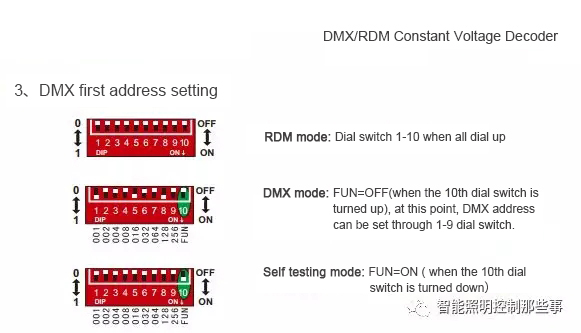
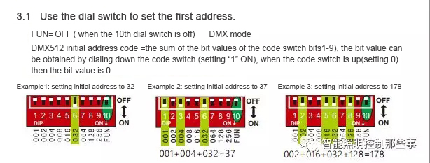
1. Traditional DMX dialing address
method diagram:
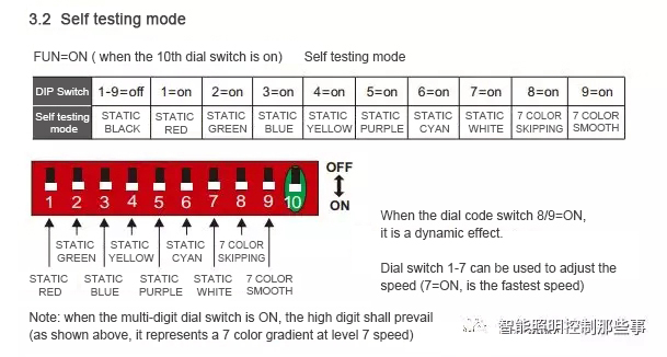
2. New digital tube DMX address setting method:
The decoder has3 keys, respectively M, +, -; long press “M” for 2 seconds to enter.
Three-digital-display indicates the current setting value; different value indicates different operating status.
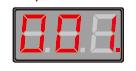
DMX
Slave Mode: The value is: 001-512, such as: “001”.
3. Schematic diagram of DMX512 decoder connection
1) Wiring diagram of Master Mode:(Only one decoder is allowed to work as a master)
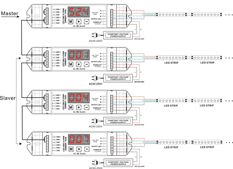
2)Wiring diagram of Slave Mode:

* More than 32 DMX decoders need to be connected with a signal amplifier, the signal amplification can not be more than 5 times.
*When the signal wire is longer or wire quanlity causes such a recoil effect, can try connect 0.25W 90-120Ω terminal resistance to the DMX decoder end line or the signal terminal of power supply to solve the problem.
bc@bincolor.com
Let’s work together to find the best solutions for your needs.
0756-3338971
Time:8:30-17:30

Copyright © 2010-2026 www.bincolor.com All Rights Reserved. 粤ICP备14037041号
Zhuhai Bincolor Electronic Technology Co., Ltd.-profrssional LED Controller R&D and manufacturer